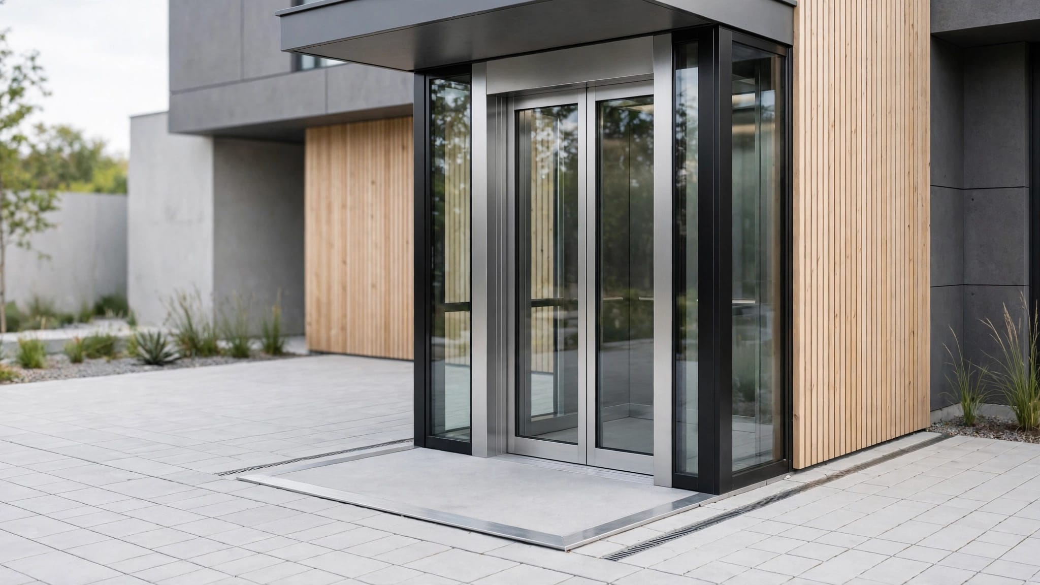

An outdoor elevator can fit a home perfectly on paper and still fail during installation because of one missed dimension, utility, or drainage problem. A careful outdoor elevator site survey turns the property into verified information that the manufacturer, engineer, electrician, and local authority can use.
Builders should survey more than the lift footprint. The team needs to confirm how the lift will be used, where loads will transfer, how people and equipment will reach each landing, and how the system will handle outdoor exposure. Use this checklist before finalizing plans or pouring concrete.
Key Takeaways
- Confirm the lift type, capacity, travel distance, landing use, and rider requirements first.
- Record finished-floor elevations, landing dimensions, overhead clearance, obstructions, and access routes.
- Have a structural engineer verify the foundation, wall attachments, wind loads, and existing framing.
- Have the elevator manufacturer confirm equipment dimensions, clearances, anchoring, gates, and operating requirements.
- Give the electrician and local authority having jurisdiction a complete survey package before construction begins.
Start With the Lift's Intended Use
The correct site layout depends on what the elevator will carry. A lift for groceries and luggage may need a different platform, gate arrangement, and operating classification than one used for building materials or wheelchair access.
Meet with the owner, architect, and elevator manufacturer before taking final measurements. Document the expected load, frequency of use, number of stops, and users at each level. Include bulky items such as appliances, lawn equipment, wheelchairs, carts, or construction materials. A stated capacity of 750 or 1,000 pounds doesn't automatically describe the usable platform size or the required structure.
Confirm whether the project needs a cargo lift, a passenger-compliant elevator, or a vertical platform lift (VPL). Product classification, rider access, controls, doors, gates, and safety systems must match the intended use and local approval path. Builders planning to move tools, supplies, or household materials can review available residential cargo lifts while developing the project brief.
Ask the manufacturer to provide the current equipment drawing before the survey. The drawing should identify the tower or rail arrangement, platform size, landing interface, overhead requirements, base connections, power needs, and any required enclosure. Surveying against an old brochure or a preliminary sketch can create expensive rework.
Measure the Installation Zone and Travel Path
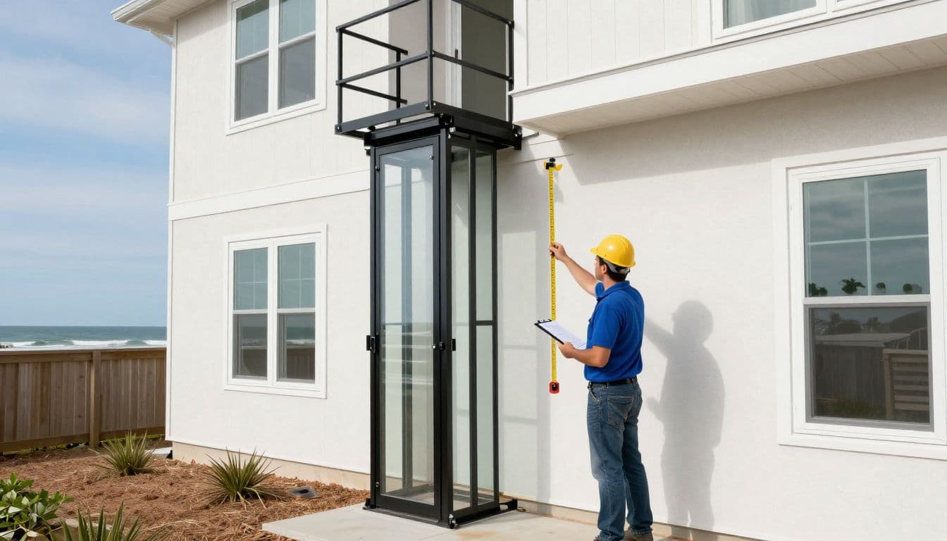
Begin at the proposed lower landing and follow the lift's full vertical route. Measure finished floor to finished floor at every stop. Grade alone isn't enough because decks, porches, slabs, and interior floors may have different thicknesses and elevations.
Record each landing's width, depth, approach direction, and usable turning space. Note whether a wheelchair, hand truck, or loaded cart must turn before entering the platform. Measure door and gate openings, swing directions, guardrails, handrails, stairs, and nearby wall faces. The manufacturer must verify the minimum clearances for the selected equipment.
Mark every obstruction along the route. Common conflicts include:
- Windows, exterior doors, shutters, and storm panels
- Roof eaves, soffits, balconies, and upper-level decks
- Gutters, downspouts, hose bibs, electrical panels, and exterior lighting
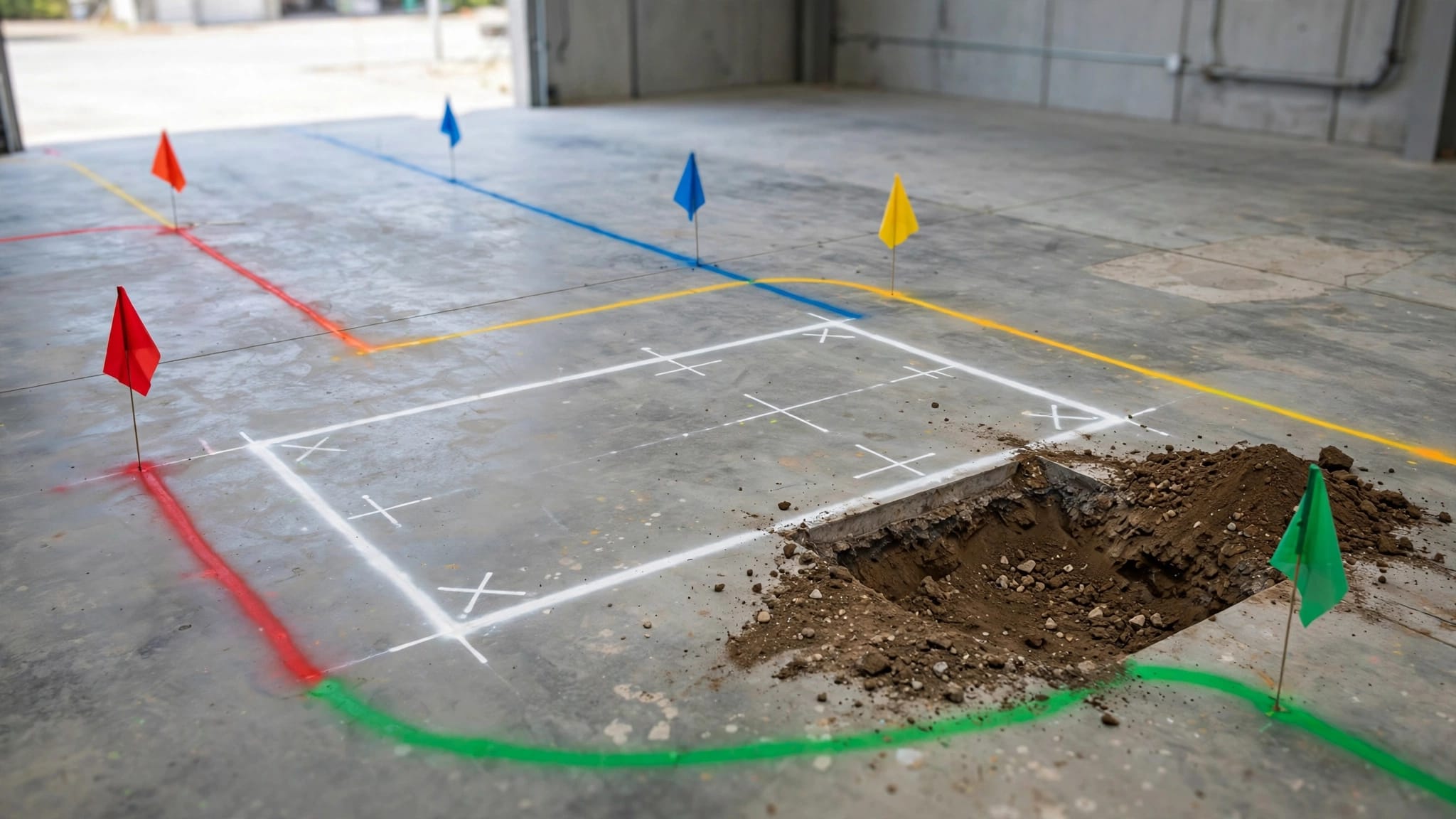
- Gas lines, plumbing, irrigation, septic components, and buried utilities
- Stairs, retaining walls, pool barriers, landscaping, and property lines
Measure the proposed lift line at several points, not only at the bottom and top. An exterior wall can change direction, lean, or include offsets that affect rails and landing connections. Record the wall construction, cladding thickness, trim depth, and any cavity behind the finish.
Take wide photographs of the entire elevation, then closer images of every connection point. Include a tape measure or marked reference in important photos. Label each image by elevation and location, and add a simple site sketch with north direction, property lines, nearby structures, and proposed travel path.
The elevator manufacturer should review all measured clearances. The architect or builder should then coordinate the final landing details with the structural and accessibility drawings.
Trace the Load Path Before Pouring Concrete
An outdoor elevator transfers more than vertical weight. The foundation and attachment system may also receive lateral forces, equipment vibration, wind effects, and impact from daily use. The finished design must show how those forces move through the lift structure and into suitable soil or supporting framing.
Inspect the proposed base area for settlement, cracks, erosion, standing water, exposed reinforcement, and previous repairs. Record whether the lift will sit on a new foundation, an existing slab, a deck, a seawall-related structure, or another support. Never assume an existing slab can support the equipment because it looks thick or intact.
The structural engineer should verify:
- Soil conditions, bearing assumptions, settlement risk, and foundation type
- Concrete strength, reinforcement, anchor layout, and edge distances
- Attachment points in masonry, concrete, timber, or structural steel
- Wind and lateral loads for the site and selected lift
- Existing framing, deck beams, headers, and load-transfer details
- Penetrations through walls, floors, roofs, and waterproofing layers
For elevated or coastal homes, inspect the supporting structure for corrosion, moisture damage, loose connections, and past storm repairs. Photograph exposed framing and note the material at every proposed attachment. If the wall finish hides the framing, plan exploratory openings or use approved locating methods before drilling.
The manufacturer must supply the loads, anchor requirements, connection details, and foundation dimensions. The engineer must decide whether the existing structure can carry them. Those roles are separate, and neither should be replaced by field judgment.
| Survey item | Primary verifier | Field information to record |
|---|---|---|
| Equipment loads and anchor forces | Elevator manufacturer | Current drawings and reaction data |
| Foundation and structural support | Structural engineer | Soil, framing, reinforcement, and attachment |
| Power and disconnect location | Licensed electrician | Service, circuit route, voltage, and equipment location |
| Permits and approval path | Local authority having jurisdiction | Required reviews, inspections, and site constraints |
A foundation detail should not be released for construction until the equipment drawing and structural design agree. Changes to platform size, travel height, enclosure, or landing position can change the support requirements.
Review Power, Drainage, and Outdoor Exposure
The electrical survey should start at the proposed equipment location and end at the service or distribution point. Identify the panel that will supply the lift, the approximate conduit route, disconnect location, control locations, and access for future service.
The electrician must verify available capacity, voltage, phase, overcurrent protection, grounding, disconnect requirements, and local outdoor wiring rules. The elevator manufacturer must confirm the equipment's electrical specifications. If the project includes emergency lowering, battery operation, generator power, or another backup system, document how that equipment will connect and where it will sit.
Keep conduit and controls away from areas where water collects or where landscaping equipment can damage them. Mark existing panels, meters, communications equipment, exterior receptacles, and generators that could conflict with the installation.
Drainage problems often appear after the lift is installed, when runoff reaches the platform or foundation. Record roof discharge, deck drainage, irrigation spray, grade direction, stormwater flow, and the location of nearby drains. Check for low points below each landing and around the proposed base.
The site survey should show how water will move away from the equipment without undermining the foundation or wetting electrical components. The manufacturer should identify any drainage or enclosure limits. The architect, civil designer, or engineer should coordinate grading, waterproofing, and discharge details.
Coastal exposure deserves its own review. Note salt spray, open wind exposure, flood-related site conditions, corrosion on nearby fasteners, and the need for storm preparation or protective covers. The manufacturer must confirm suitable materials, finishes, operating limits, and shutdown procedures for the selected location. Do not treat a generic exterior finish as proof of suitability for every coastal site.
Plan Construction Access and Safe Landings
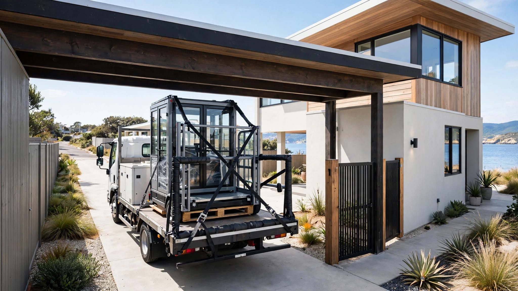
Measure the route for delivery, assembly, and service, not only the final platform. Record gate widths, driveway slopes, parking limits, overhead wires, low branches, narrow side yards, and the distance from unloading areas to the foundation. Large components may require a forklift, crane, telehandler, or other lifting method approved for the site.
Confirm where materials can be staged without blocking residents, emergency access, neighboring property, or public walkways. Identify temporary protection for finished walls, decks, landscaping, and waterproofing. If the lift will be installed beside an occupied home, establish a safe separation between construction activity and residents.
Every landing needs a clear approach and a safe interface with the building. Check finished floor heights, thresholds, guard conditions, gate locations, lighting, drainage, and the direction of travel. The manufacturer must verify gate and interlock requirements. The architect and local authority must verify accessibility, egress, fire separation, and other building conditions that apply to the project.
Mark overhead hazards before lifting components. Include utility lines, roof edges, balconies, and temporary scaffolding. Coordinate the work sequence so the crew doesn't install a landing before the wall, waterproofing, electrical rough-in, or structural reinforcement is ready.
A good survey answers two questions before construction starts: where does the equipment fit, and what must support and power it?
Turn Field Notes Into an Install-Ready Package
A survey becomes useful when another professional can review it without returning to the property for basic answers. Assemble one package with a dimensioned plan, elevation views, photographs, equipment drawings, utility information, and a list of unresolved conditions.
Include finished-floor elevations for every stop, proposed platform and landing dimensions, wall offsets, overhead measurements, foundation location, access route, and service clearances. Add the date of the survey and identify whether dimensions are existing, estimated, or based on a proposed finish.
Before releasing the package, verify that:
- The lift type and intended load match the owner's use.
- Every landing has a measured elevation and approach dimension.
- The proposed travel path avoids known utilities and building obstructions.
- Foundation and attachment conditions have reached the structural engineer.
- Power information has reached the electrician.
- Equipment clearances and connection details have reached the manufacturer.
- Permit and inspection questions have reached the local authority having jurisdiction.
- Finish thicknesses, drainage, storm protection, and service access appear on the drawings.
Use one revision-controlled drawing set. If the architect changes a deck, wall finish, roof edge, or landing door after the survey, update the dimensions and send them back for review. The manufacturer's elevator installation process can help the project team align manufacturing, site preparation, and installation milestones.
Do not approve concrete, framing, conduit, or landing finishes from verbal assumptions. Put dimensions and responsibilities in writing, then obtain the required sign-offs before work begins.
Conclusion
A reliable outdoor elevator site survey gives the project team a shared set of facts. It records the lift's purpose, the complete travel path, finished elevations, structural support, power route, drainage, exposure, and construction access.
The builder coordinates the information, but each specialist must verify the part that affects their work. When the manufacturer, structural engineer, electrician, architect, and local authority review the same accurate package, the installation has a far better chance of fitting correctly the first time. The missed measurement that causes trouble later is usually easy to capture during a careful survey.
Recent Posts