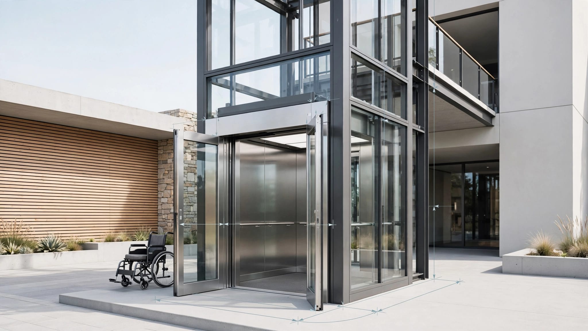

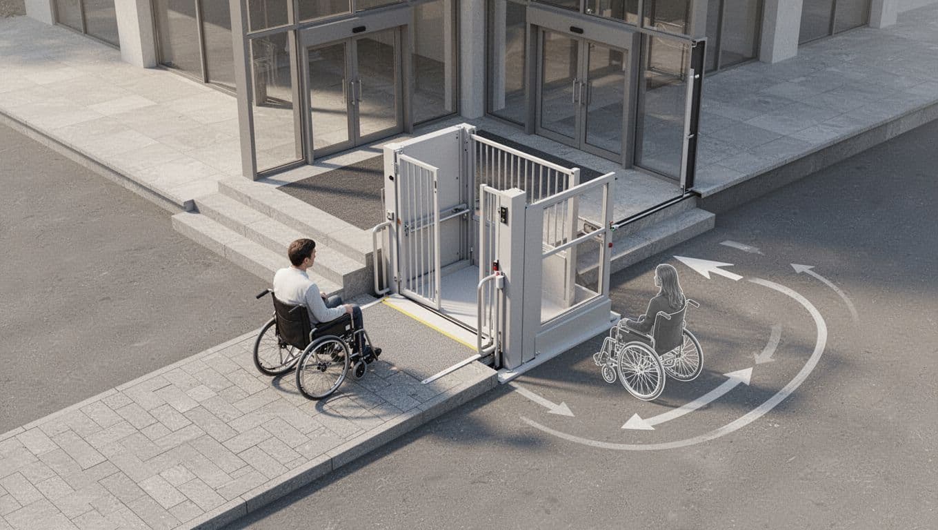
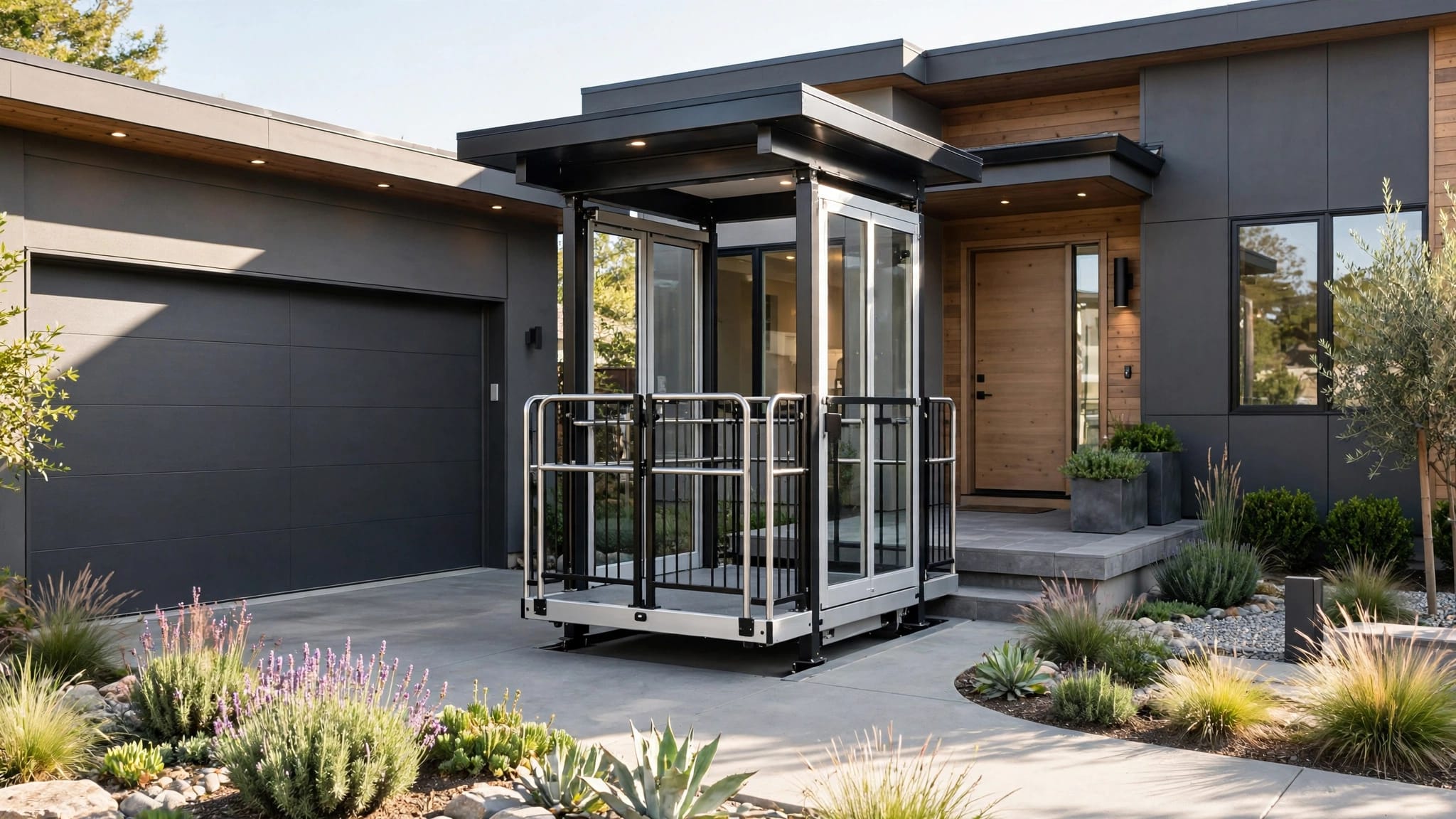
An outdoor VPL can make a raised entry usable, but a platform that fits a wheelchair doesn't prove the surrounding layout works. The VPL turning space must let a wheelchair user align with the gate, enter without a sharp correction, exit onto a level landing, and change direction when the route requires it.
The central planning mistake is treating the lift platform, landing, and turning area as one measurement. ADA 2010 Standards, ICC A117.1, ASME A18.1, the lift manufacturer's drawings, and the local authority having jurisdiction can control different parts of the design. Start by separating the spaces, then test the complete movement path.
VPL Turning Space and Landing Dimensions Are Different
These areas work together, but they don't have the same function. A drawing should identify each one before the lift location is finalized.
The landing is the entry and exit zone
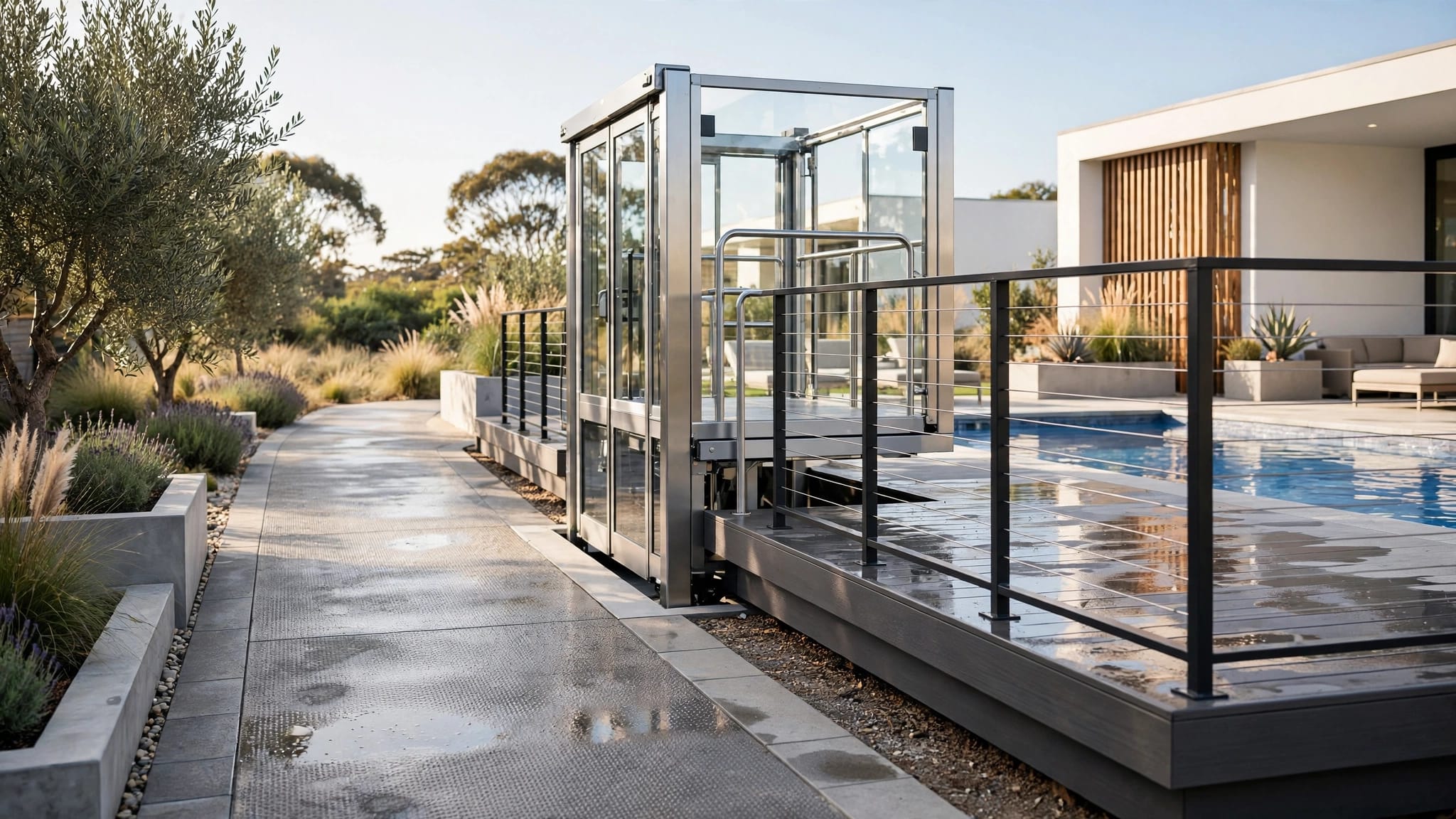
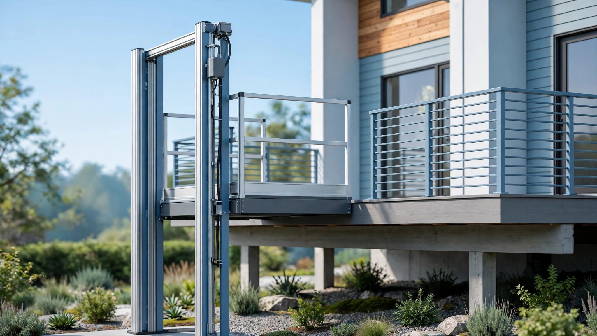
A landing is the level surface directly outside the VPL platform. At the lower level, it connects the walkway, driveway, or porch approach to the lift. At the upper level, it connects the platform to the deck, balcony, doorway, or accessible route.
The landing must accommodate the actual gate or door opening, the threshold, guardrails, handrails, and any nearby wall or post. Its finished surface also needs proper drainage and a stable, slip-resistant walking area.
A landing may be large enough to include turning space, but that isn't automatic. A platform dimension that works for entry doesn't prove that the user can turn after leaving the lift.
Turning space is the maneuvering area
Turning space is the unobstructed area where a wheelchair user changes direction. The common ADA baseline is a 60-inch diameter turning circle or a permitted T-shaped turning space with the required clear dimensions.
A VPL turning space may overlap the landing when the entire area remains clear. However, the gate swing, door swing, railing, control box, drain, furniture, and structural posts cannot reduce the required maneuvering area.
Minimum Dimensions to Place on the Drawing
Use the following values as a starting point for a U.S. accessibility layout. They are not a substitute for the adopted code, the selected lift's specifications, or the AHJ's review.
| Design element | Minimum or reference value | How to apply it |
|---|---|---|
| Platform clear width | 36 inches minimum in U.S. Access Board platform-lift guidance | Maintain this clear width through the lift opening. |
| End-door platform length | 48 inches minimum | Applies when the door or gate is on the narrow end. |
| Side-door platform length | 60 inches minimum | Accommodates side-approach maneuvering at the platform. |
| General clear floor space | 30 by 48 inches minimum under ADA Section 305.3 | Use for accessible elements, but don't treat it as the complete VPL layout. |
| Wheelchair turning space | 60-inch diameter common ADA baseline | A compliant T-turn may be allowed where the adopted standard permits it. |
| Platform-to-landing gap | 1 1/4 inches maximum under ADA platform-lift guidance | Verify the equipment's tighter installation limits under ASME A18.1. |
| Platform area | 18 square feet maximum is commonly cited in federal platform-lift guidance | This controls the platform, not the landing. Confirm the lift model and code edition. |
Straight-through and side approaches
A straight-through arrangement usually needs less maneuvering space than a side approach. When the user approaches the narrow end of the platform, the Access Board guidance identifies a 36-inch minimum clear width and 48-inch minimum clear length.
A side-entry configuration needs more depth because the wheelchair must approach, align with the opening, and turn or reposition beside the platform. The referenced baseline is 36 inches wide by 60 inches long. The landing outside the platform may need additional space for a door, gate, route, or turn.
Why adopted codes may produce different dimensions
ADA is the federal accessibility baseline for covered facilities, while ICC A117.1 can add detailed requirements through the building code adopted by a state or local jurisdiction. The applicable edition matters.
For example, 2009 ICC A117.1 provisions for platform lifts with doors on adjacent sides show a 42-inch minimum clear width by 60-inch minimum clear depth, with an existing-building exception of 36 by 60 inches. Update material for the 2017 edition identifies a 36 by 52-inch new-building clear floor space and a 67-inch new-building turning space, compared with 60 inches for existing buildings.
Those figures aren't universal replacements for ADA dimensions. Confirm the edition listed in the project code analysis before placing them on construction documents.
How a Wheelchair User Approaches and Leaves the Lift
A good layout follows the user's actual movement instead of measuring only the lift enclosure. The path should work at both levels, including the approach before entry and the space available after the gate opens.
Lower approach and entry
The wheelchair user should be able to approach the lower landing with enough straight, unobstructed space to align with the platform opening. A sharp turn immediately before the gate can make a technically adequate platform difficult to use.
Check the approach for walls, railings, planters, downspouts, parked vehicles, steps, and changes in surface elevation. A gate or door must provide the required clear opening, and its swing should not reduce the required landing or maneuvering area.
Controls should remain reachable without forcing the user to lean into the gate path. The final threshold and sill relationship also matter. A gap that looks minor on plan can catch small front casters or interfere with an occupant's entry.
Upper exit and turning movement
At the destination level, the user exits onto the upper landing and either continues along the accessible route or changes direction. If the lift sits at the end of a narrow porch, the user may need a 60-inch turning circle or an approved T-shaped alternative outside the gate.
The platform itself shouldn't be treated as the only place to turn. Its size may be limited by ADA guidance and ASME A18.1, while the user may need to maneuver after leaving the platform. Place the turning area where the chair will actually change direction.
Recommended Allowances for Outdoor VPL Layouts
Minimum dimensions are useful for code review, but tight layouts can become difficult after construction adds rails, trim, gates, drainage, and finishes. Mark required clear areas separately from surrounding construction space.
| Site condition | Minimum or reference point | Recommended planning allowance |
|---|---|---|
| Straight-on platform entry | 36 by 48 inches for the referenced end-door platform arrangement | Add space for the gate, threshold, and a clear approach. Don't assume this area provides a full turn. |
| Side-entry platform | 36 by 60 inches in the referenced guidance | Reserve at least 60 inches of clear length, then test the full wheelchair path. |
| User must reverse direction | 60-inch circle or compliant T-turn | Keep the complete turning area outside gate swings, rails, posts, and door maneuvering zones. |
| Door near the lift | Door clearances under the adopted accessibility code | Coordinate the door and lift before framing the landing. |
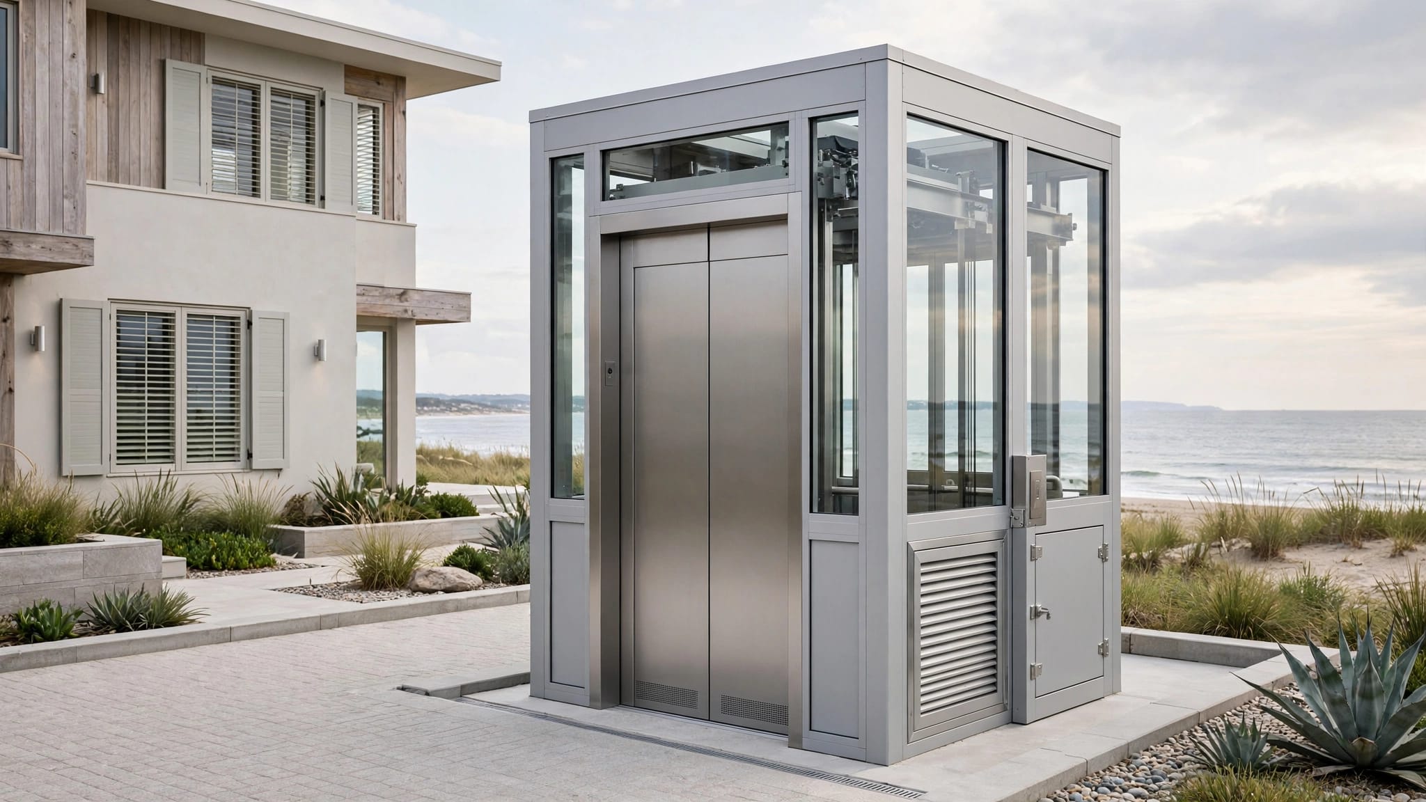
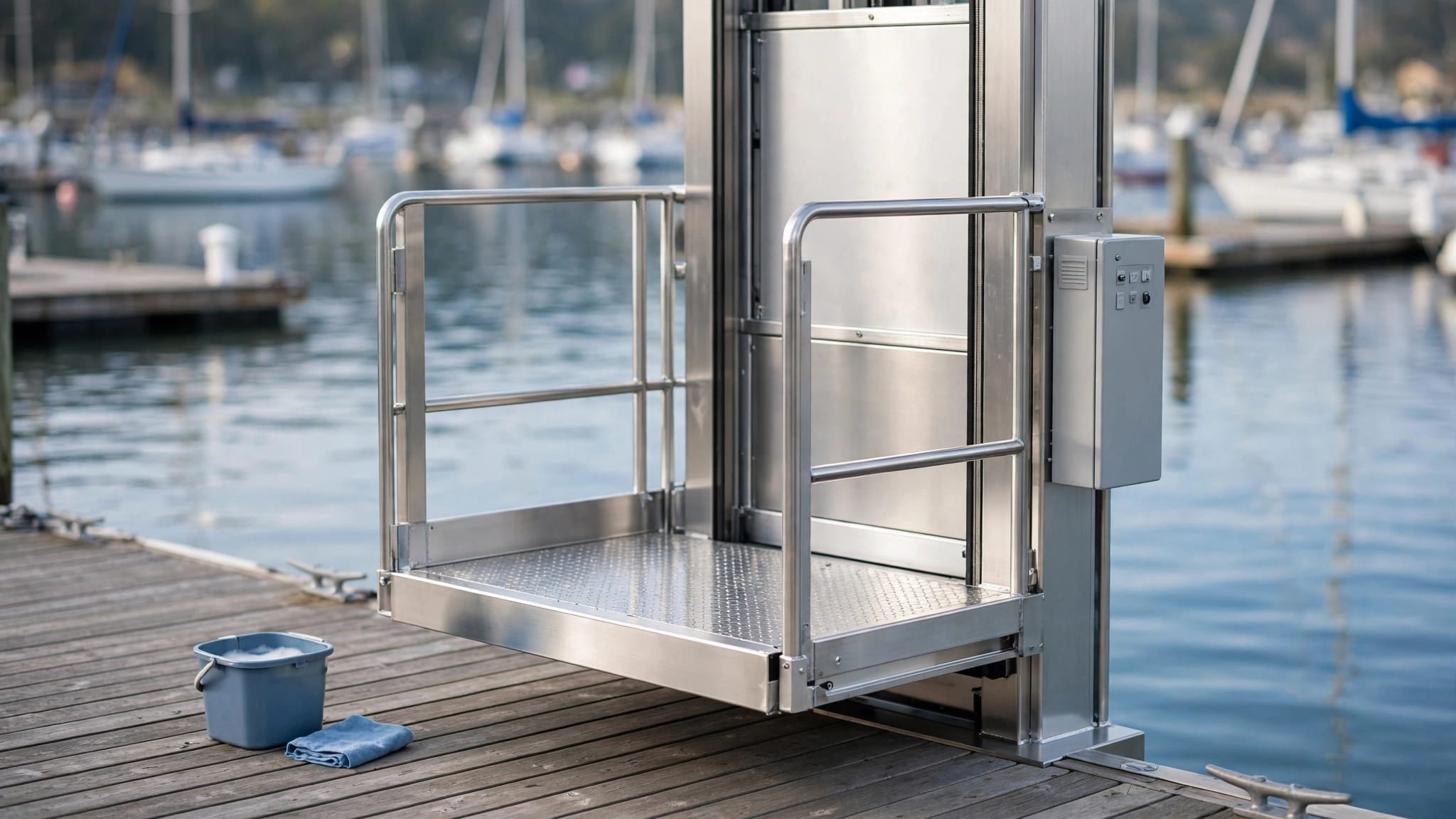
| Coastal or exposed site | Project-dependent structural and drainage review | Allow for corrosion protection, wind exposure, rain, sand, and maintenance access. |
Leave room for the built environment
The finished clear area can shrink when guardrails, handrails, gate frames, columns, siding, or electrical equipment are installed. Dimension between finished obstructions, not between rough framing lines.
A landing also needs a practical relationship with the building door. If the door opens across the approach, the wheelchair user may have to occupy the same space needed for the door maneuver. Resolve that conflict in plan view before construction.
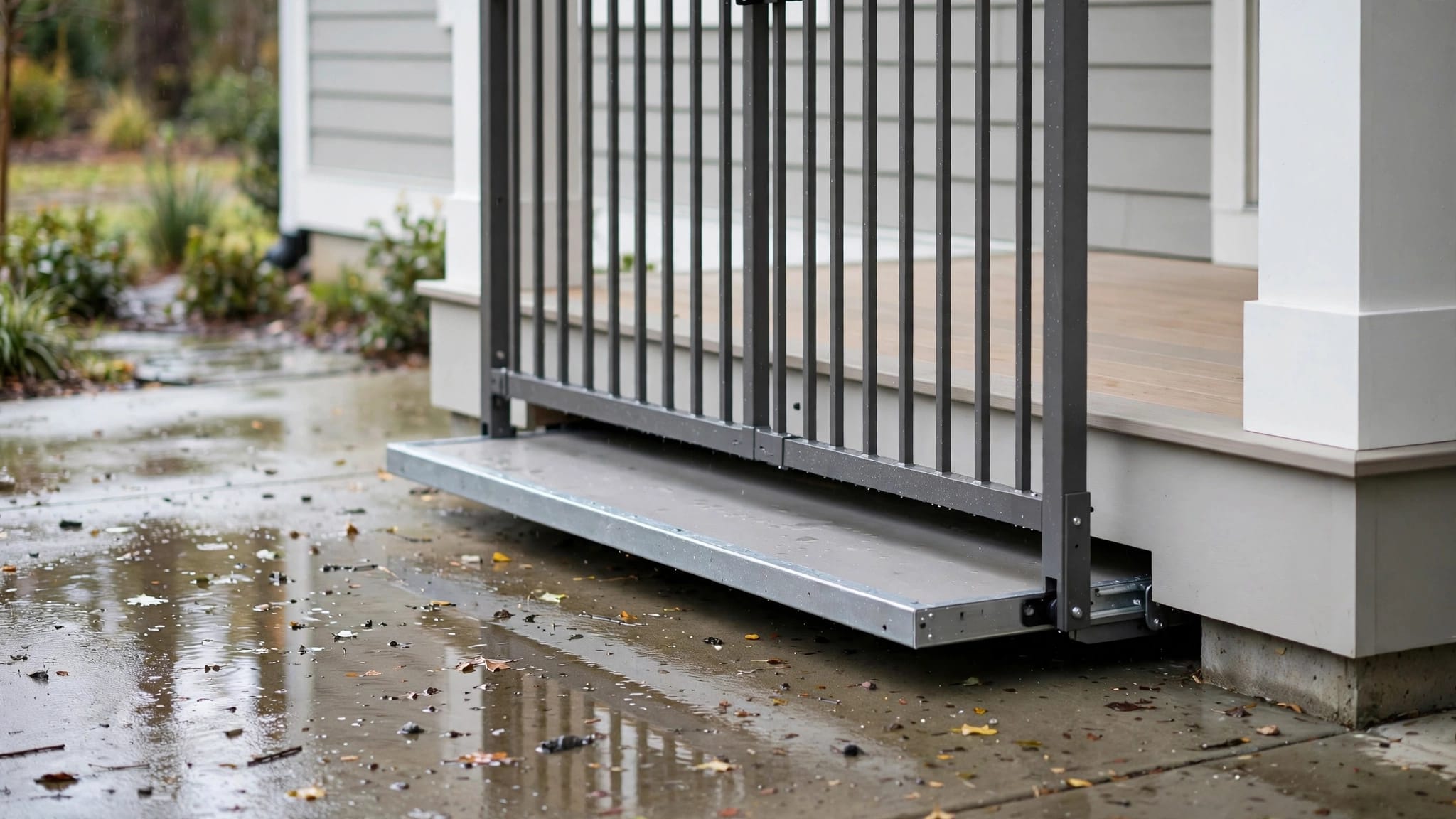
Outdoor drainage creates another design constraint. Keep water from collecting at the sill or flowing across the landing. Use a surface treatment and slope that comply with the adopted accessibility requirements and the lift manufacturer's installation instructions.
Confirm the Design With the Manufacturer and AHJ
Start with the selected lift
Manufacturers provide the actual platform dimensions, clear gate opening, sill details, control locations, guard requirements, and structural attachment points. Those dimensions can vary by model and configuration.
Before pouring a slab or building a deck, use an outdoor VPL platform size guide to document the lower and upper approaches. Then compare the proposed layout with the manufacturer's shop drawings.
ASME A18.1 controls lift safety details such as platform construction, gates, enclosures, interlocks, and running clearances. It doesn't replace the site-specific accessibility review for the surrounding landing.
Keep the code path clear
Identify whether the project falls under ADA, an adopted building code using ICC A117.1, state accessibility rules, or another standard. Commercial work, public facilities, multifamily housing, and private residences can follow different approval paths.
The AHJ may also review egress, fire separation, guardrails, structural support, electrical work, flood conditions, and permit requirements. A dimension that works under one code edition may not satisfy another jurisdiction or occupancy type.
Practical Outdoor VPL Layout Checklist
Use this checklist during design review and again after installation:
- Confirm the adopted accessibility standard, building code edition, occupancy classification, and AHJ.
- Record the lift model, platform clear width, platform length, gate location, and clear opening.
- Draw the lower and upper landings using finished dimensions.
- Mark the approach path, entry path, exit path, and required turning area.
- Test a 60-inch turning circle or the applicable T-shaped turning space.
- Check door swings, gate swings, handrails, guardrails, posts, planters, drains, and control boxes.
- Verify the platform sill, landing threshold, gap, level relationship, and surface conditions.
- Check drainage, lighting, weather exposure, maintenance access, and emergency access.
- Compare the drawing with the manufacturer's approved layout before construction.
- Measure the completed installation after rails, gates, paving, and finishes are in place.
A site survey checklist for outdoor lifts can help the project team capture these conditions before ordering equipment.
Conclusion
A wheelchair lift platform, its landing, and the surrounding turning area each answer a different design need. The platform carries the user, the landing provides a level entry and exit zone, and the turning space allows the wheelchair to change direction safely.
Use the 36-inch width, 48-inch end-entry length, 60-inch side-entry length, 60-inch turning circle, and 1 1/4-inch maximum sill gap as initial reference points. Then verify every dimension against the adopted code, lift manufacturer, and local authority having jurisdiction. A successful outdoor VPL layout is measured by the complete movement path, not by the platform alone.
Recent Posts